Animatronic Mouse House
This post documents the overall build process of an animatronic mouse house hidden inside a wall. This animatronic mouse has 3 degrees of freedom driven by an ACME lead screw stepper motor and two servo motors inside the body of the puppet. To preserve the integrity of the mouse puppet, a key design feature is how the door opens by utilizing a timing belt to open the door just before the mouse’s snout makes contact avoiding deformation of the puppet’s face.
Unlike some of my other projects, I will not be publishing all the CAD models immediately, this may however change in the future. Nonetheless, I hope this project inspires you to create your own animatronic projects.
Components:
(contains affiliate links)
Finger Puppet Mouse: https://amzn.to/338zZcc
Arduino Uno: https://amzn.to/3EXyKtC
200mm Guide Rail Set: https://amzn.to/3EU8Cj3
Stepper Motor and TB6600 Driver: https://amzn.to/331ZtrA
SG90 Servo: https://amzn.to/3t20PgR
12V Power Supply: https://amzn.to/3qZfDKO
Optical Limit Switch: https://amzn.to/3eVtTOX
5mm Flange Bearing: https://amzn.to/3eX31xS
GT2 Timing Belt and Pulley: https://amzn.to/338Mowv
M4 x 8mm Socket Head Screw: https://amzn.to/3t2NncO
M3x0.5 & M4x0.7 Heat Set Inserts: https://amzn.to/3HEoxnp
5mm Flange Hub: https://amzn.to/3zwg5DX
5mm Diameter Rod: https://amzn.to/336bNHa
Acrylic, scrap wood, PLA filament, assorted screws, wire, 7805 voltage regulator, cable management: (no link provided)
Overview of the Mechanical Assembly
Below is a CAD model of the mouse house assembly. The stepper motor (bottom left) drives a lead screw that in turn moves a large carriage assembly made of 4mm white acrylic and black PLA 3D printed parts. This structure connects two blue SG90 servos (in the top right) and ensures they clear over the top of the miniature staircase (on the outside of the door - not shown in this picture).
The stepper motor is controlled via a TB6600 stepper motor driver and Arduino Uno. There are optical limit switches at either end of the linear rail assembly to detect when the direction needs to be reversed.
You may also notice the vertical 5mm diameter metal rod connected via a slider-crank linkage just to the left of the large carriage assembly, I will dive into this component in more detail later, but in short, this 5mm rod is connected to the door hinge via a GT2 timing belt and opens the door so the mouse doesn’t use its face to push the door open.

Figure 1: CAD model
Mouse Puppet Taxidermy
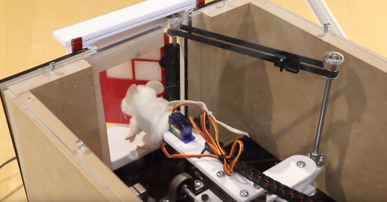
Without a doubt, the most important part of this creation is the finger puppet mouse. The puppet is just wide enough to fit two SG90 servos inside to control the head and body (up/down and left/right motion, respectively). In an ideal world, the length of the puppet would be a little longer to hide the mechanical elements a little better.
The wires coming out of the two SG90 servos connect to the Arduino Uno via a drag chain cable to ensure the wires are not damaged, fatigued, or caught during thousands of actuation cycles.
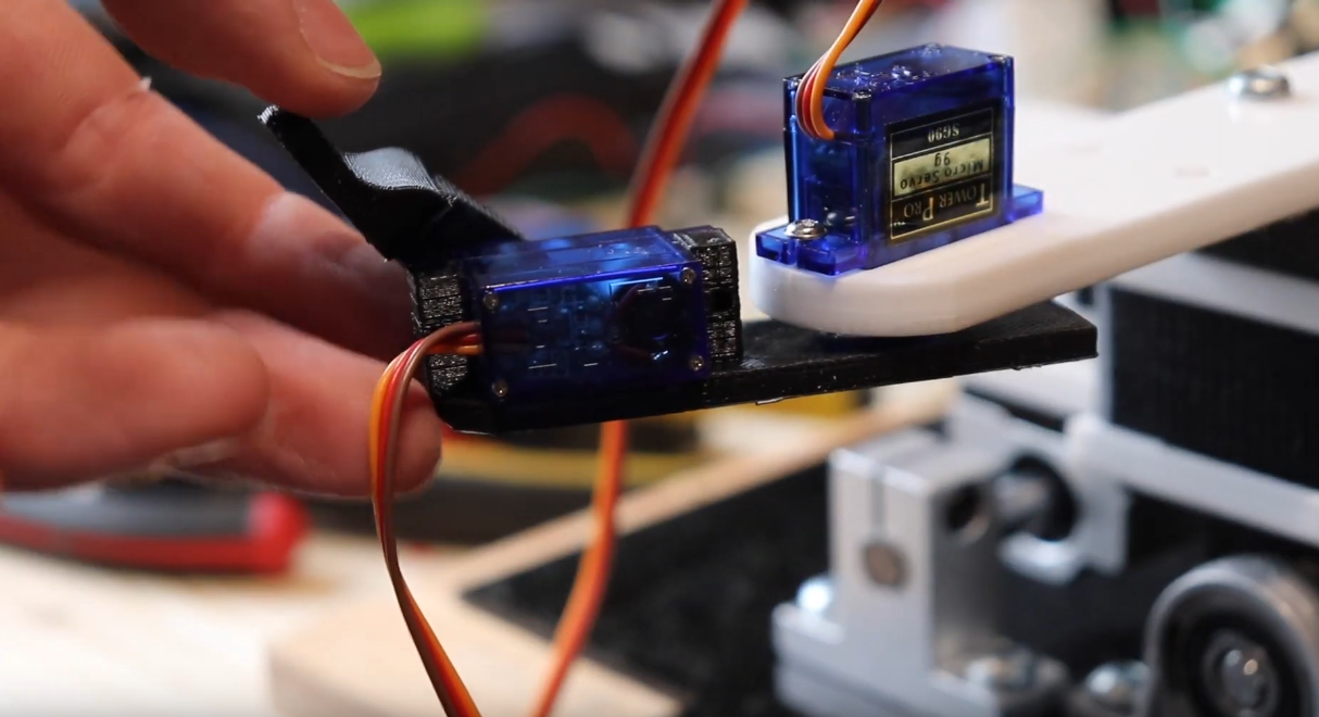
Figure 2: Skeletal frame of puppet mouse body
Stepper Motor Linear Actuator
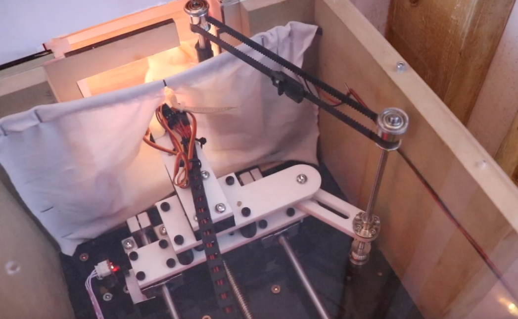
To assemble the carriage that attaches to the mouse I used a fairly standard 200mm linear guide commonly used in 3D printing and CNC applications. I also used brass heat-set inserts, pressed into 3D printed parts with a hot soldering iron, to ensure the M3 and M4 bolts would securely hold everything in place (Figure 3 and 4).
Ensuring the optical guide rails are perfectly parallel is critical to avoid binding the carriage. To achieve this I use a laser cutter to cut a piece of 3mm black acrylic into what is effectively a template, ensuring that when each component is attached, everything will remain aligned.
One weakness of my design was using plywood as the base plate. At timestamp 1:35 in the YouTube video it is clear that the stepper motor “wiggles” as it drives. This is due to the soft nature of the plywood, and while this installation ran for several hours a day for a month without fail (estimated 18,000 cycles), in the future I would like to improve this by replacing the wooden base (Figure 5).
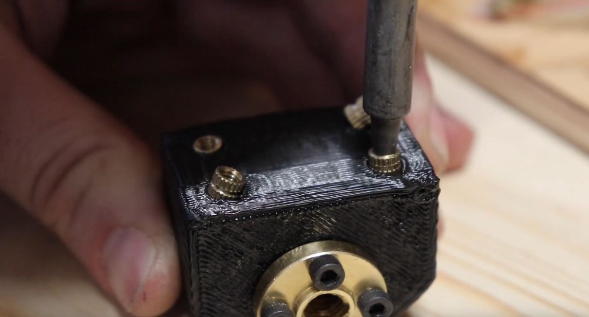
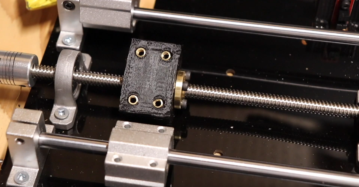
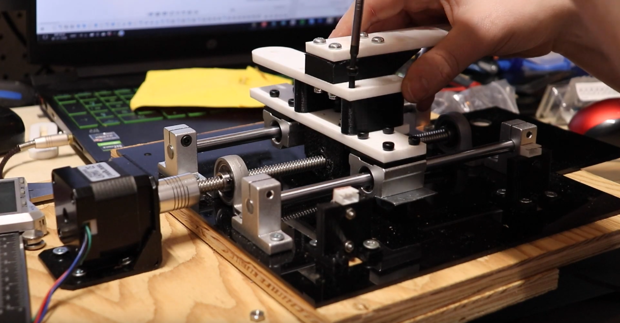
Figure 5: Sliding carriage assembly
Swinging the Door Open
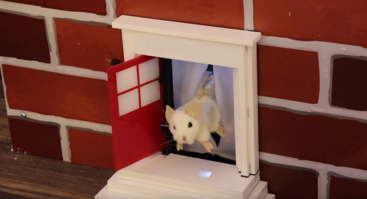
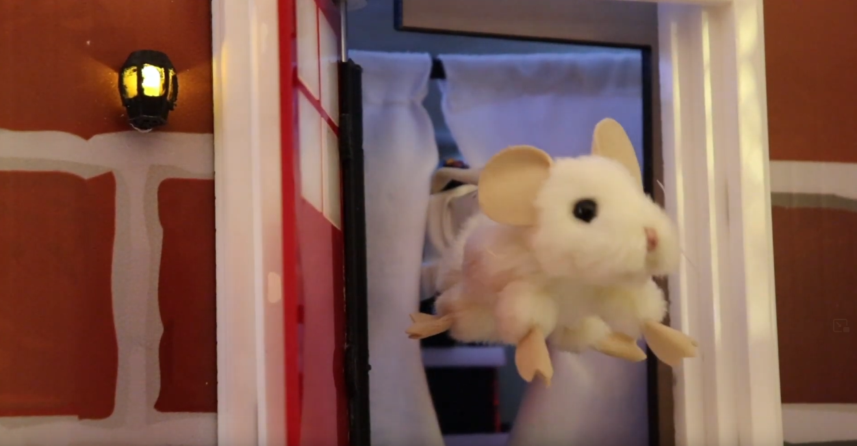
I initially planned to use a spring to keep the door closed and the mouse would physically push the door open as it extended out of the house. This plan was quickly abandoned for two reasons, firstly, the mouse’s snout would quickly become deformed and secondly, when the mouse made contact with the spring-loaded door, most of the mouse’s body would be hidden from view. I moved towards a different design that ensures the mouse is clearly visible and the door opens wide (Figure 6).
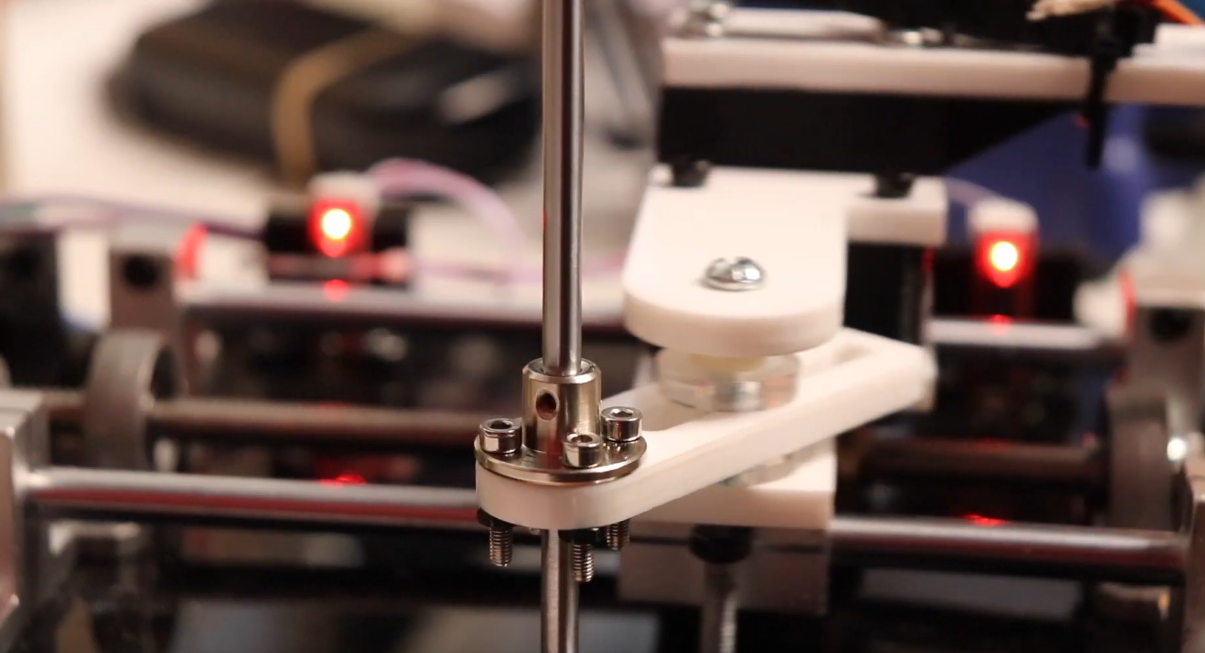
To achieve this I laser cut a slider-crank linkage (Figure 7) out of acrylic that would connect to a 5mm steel rod and rotate 120 degrees as the carriage slide down the linear rails. The 5mm metal rod is secured by 5mm flange bearings set into the top and bottom acrylic sheets of the outer box.
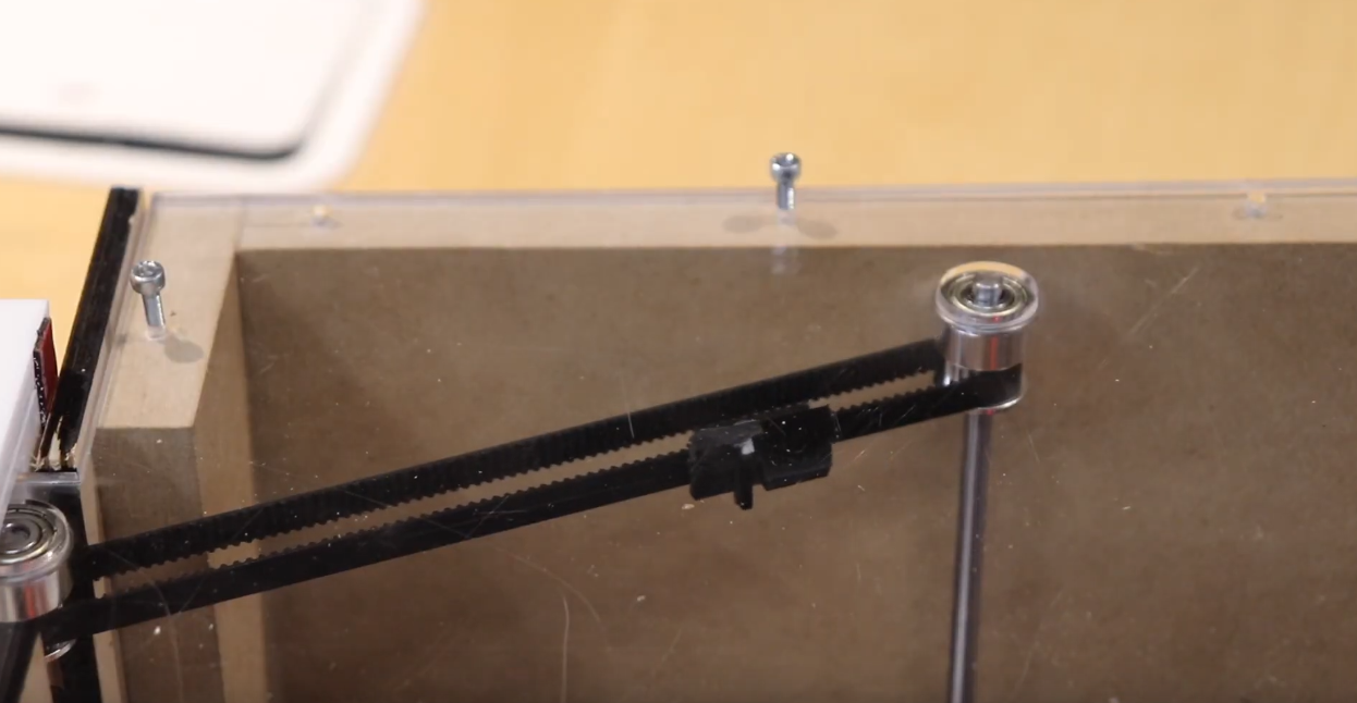
At the top of the 5mm steel rod is a pulley that connects via a GT2 timing belt to another 5mm steel rod that acts as a hinge for the door (Figure 8). The door is made of red and white 3mm acrylic with a black 3D printed bracket.
Finishing Touches
Finally, I 3D printed a small, black, lantern and inserted a yellow LED. I also added two pieces of white fabric, one on either side of the mouse, to hide the mechanical components from the audience.
Disclaimer: Links in this post may be affiliate links. If you purchase a product or service through the links I provide I may receive a small commission. This support enables me to pursue bigger and better projects. Affiliate links include no additional charge to you.