Designing a PCB in Fusion 360
This blog post is a short supplement to the 3 part video tutorial series I posted on YouTube demonstrating how to create a complete PCB from scratch in Fusion 360. The videos are largely self-contained, this blog post just provides some extra info beyond the scope of the tutorials.
Please see the GitHub repo for relevant files/code.
Part 1: Creating an Electronic Component Library
Part 2: Drawing an Electrical Schematic
Between 7:44 and 8:12 in the above video, I mention in passing the process of connecting two potentiometers to a single analog pin on the ESP8266. In this written section I will provide a little more clarity to how this works using a pair of diodes, please note that the method I used is inferior to using an analog multiplexer chip. The only reason I didn’t use an analog multiplexer chip was due to supply shortages and shipping times for the chip I wanted.
The image below shows a screengrab of the two potentiometer circuit with diodes.
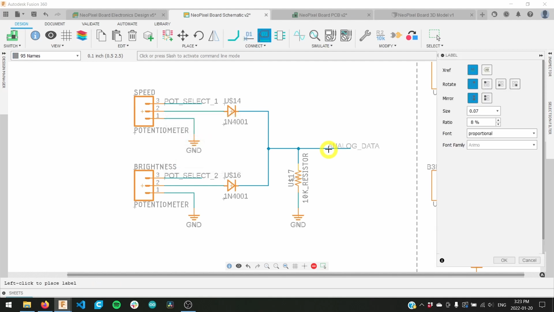
Circuit of two potentiometer inputs to one analog pin
The 1N4001 diodes act as one-way gates and by controlling the output pins POT-SELECT-1 and POT-SELECT-2 the potentiometers can be individually toggled. For example when POT-SELECT-1 is HIGH and POT-SELECT-2 is LOW then the ANALOG-DATA pin will collect user input from potentiometer 1 and visa-versa.
A sample piece of code for achieving this control is available on GitHub.
One serious limitation of this approach is the diode voltage drop. The 1N4001 diode drops around 0.7V. This seriously impacts the analog range that the ESP8266 can measure as the ESP8266 uses a 3.3V logic level. Therefore, the maximum voltage that can reach the analog input pin of the ESP8266 is 2.6V (3.3V - 0.7V), converted to an analog signal this gives a range of [0, 806] instead of the full range of [0, 1023]. Said another way, using a diode reduces the input range by 21% = (0.7V/3.3V)*100%. It is for this reason that I would recommend using an analog multiplexer IC in your projects.