Series Elastic Actuator (SEA) for Robotic Prosthetic Hand

CAD model of SEA
Traditional actuators have a motor, gearbox, and encoder making them very easy to use in robotics projects that require position or velocity control. However, while the output torque of DC motors can be controlled by monitoring their input current, it is quite difficult to do in the real world (as I discovered while working on an inverted pendulum). But by adding an elastic element (usually a spring) and encoder/potentiometer after the gearbox one can create a series elastic actuator (SEA) that can measure and control the output torque (Hooke's law). Furthermore, SEA has the desirable property of compliance.
Over 3 years ago I designed and built my first robotic prosthetic hand, and to be frank, it was pretty terrible. But it was an excellent learning opportunity, amongst the many valuable lessons I discovered the importance of torque control and compliance in robotic systems. In the case of a robotic hand, torque control is very important when picking up different objects; an egg requires a softer touch than a hammer. Additionally, compliance in a robotic hand is useful; if the hand was to impact something at a moderate force it is better to slightly and temporarily deform than to break on impact. Enter series elastic actuators, a brilliant type of actuator that resolves these two problems.
My unique design of a SEA is aimed to be small in size and cheap (<$60). The SEA will be designed to be about half the size of a whiteboard marker, such that it can fit inside the palm of the prosthetic hand, in line with its respective finger (not including the thumb). The first image (above) shows a CAD model of the assembled SEA and below is an expanded view of the individual components.
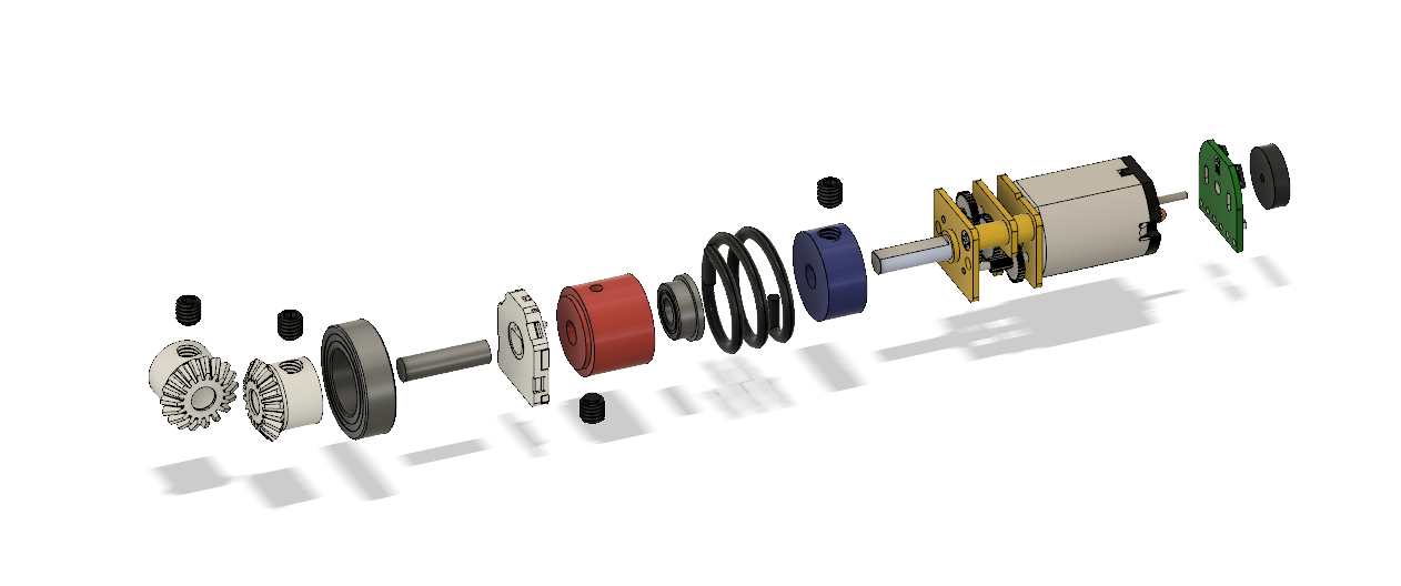
Exploded view of the SEA
From right to left the components in the image above are:
Magnetic disk
Hall effect encoder circuit
N20 micro-gear motor (multiple gear ratios are available)
Blue input frame: machined aluminum with axial hole for the motor shaft, radial holes for set screw, and torsion spring leg
Black torsion spring with legs bent radially inwards
Flange bearing with 3mm inner diameter for mounting on motor shaft and supporting the red output frame
Red output frame: machined aluminum with axial holes for a 3x11mm rod and flange bearing, radial holes for set screw, and torsion spring leg
Flat disk potentiometer
3x11mm rod
Bearing with 8mm inner diameter
Bevel gear with set screw
Output bevel gear with set screw
By measuring and calculating the angular difference between the magnetic encoder and potentiometer the spring force can be calculated $F_s=-k\theta$, thus enabling torque control when picking up objects. Note that the potentiometer does limit the output rotation to less than 180 degrees, however, since this is designed to be used in a robotic hand this is not a concern. The output bevel gear will be the knuckle of the finger, directly rotating the proximal phalange and a linkage mechanism will move the distal and intermediate phalanges. If this SEA was to be adapted to a continuous rotation application I would trade the potentiometer for a gearbox and encoder (a gearbox will give more precise readings from the encoder).